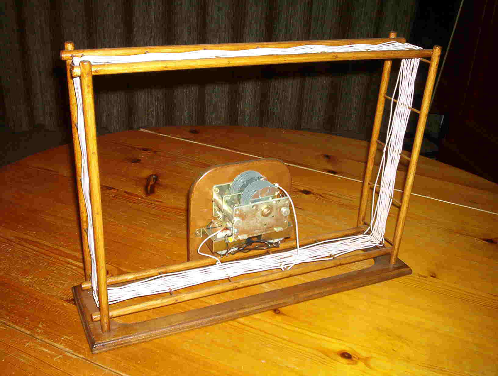
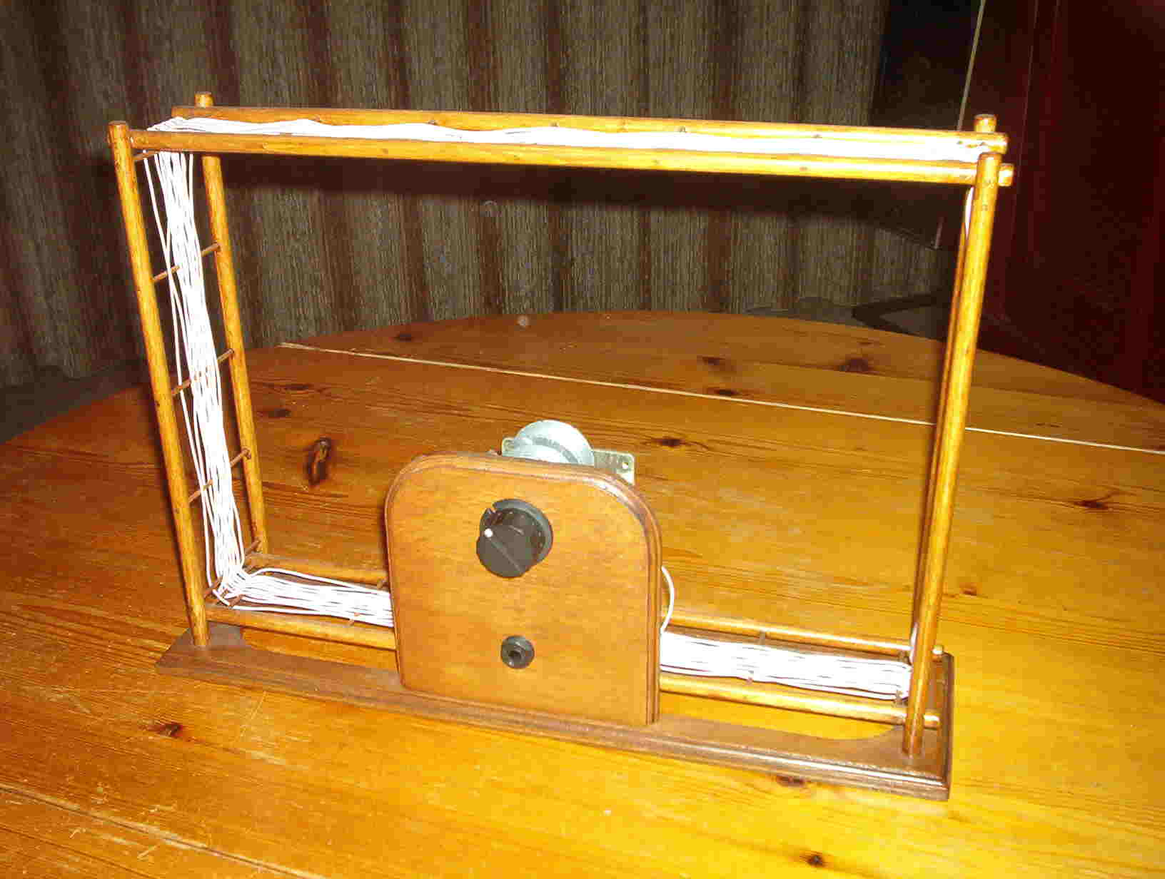
Set 10 Receiver with loop antenna
This receiver has a 26x38 cm loop antenna, made of
660x0.04 mm litzwire.
The loop antenna has 16 windings, and is wound around a frame made of wooden
sticks.
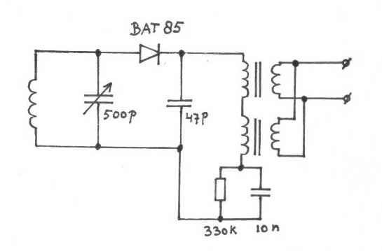 |
Circuit diagram: Set 10 |
The transformers (type: 952.431) are with the 16
Ω output windings parallel connected, this
gives an impedance of 8 Ω.
The connected headphone however gives a load which is twice as high (16
Ω).
This will make the input impedance of the transformers (normally 80 kΩ)
almost double.
The total input impedance of the two transformers will now be about 300 kΩ.
As loudspeaker, a modern headphone is used (Sennheiser model: HD202).
With this receiver I took part in the Elmar memorial
crystal radio dx contest 2006, and received 4 stations:
See the Contestlog Elmer 2006.xls
During the Dutch BTTF crystal receiver contest (december
2005) I received 6 stations with this receiver.
See the Contestlog BTTF 2005.xls
However, the number of received stations was quite low.
I measured the Q factor of the complete receiver, which
was quite low (see measurement 1).
To find out the reason, first the diode was disconnected, this increased the Q
quite a lot (measurement 2).
Then the two transformers were removed (measurement 3), because they were at
close distance to the coil, there was influence on Q factor.
The next measurements are done with 1.4 Volt peak-peak across the LC circuit
| Measurement | Q 600 kHz |
Q 900 kHz |
Q 1200 kHz |
Q 1500 kHz |
|
| 1 | Set 10 Complete receiver Loaded with headphone |
136 | 107 | 72 | 64 |
| 2 | Diode disconnected | 300 | 264 | 206 | 182 |
| 3 | Transformers removed | 500 | 388 | 285 | 214 |
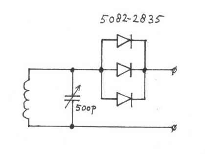
| 4 | 3x 5082-2835 diode and 1M5 load |
333 | 265 | 203 | 160 |
Then I connected 3 schottky diodes (5082-2835) in
parallel to the receiver (measurement 4).
In measurement 4, a load resistor of 1.5 MΩ is
used, because this is about the impedance of my
transformer unit1.
Set 10 version 2
Then I replaced the 1.5 MΩ resistor (measurement 4)
by the transformer unit 1, and connected a driver unit
to it.
Both sensitivity and selectivity of the receiver was now much better then first.
With this version of the receiver, I took part in 2006 in a contest, and
received 24 stations.
See the Contestlog sprint 2006.xls
 |
Circuit diagram of: set 10 version 2 At the output, transformer unit 1 is connected. |