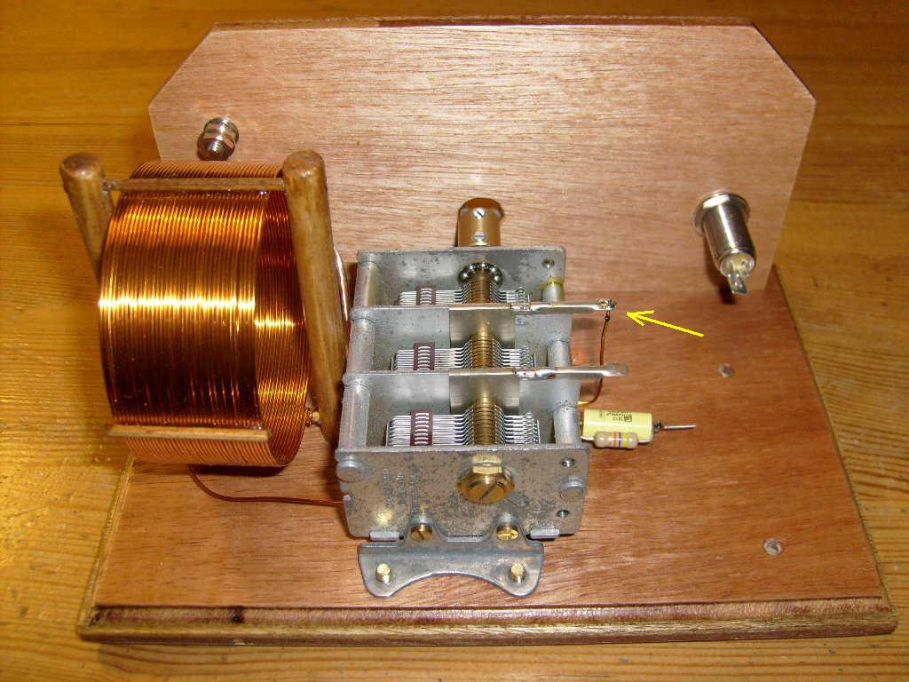
Place the tuning capacitor on the frame.
Fix it with four screws M4x16
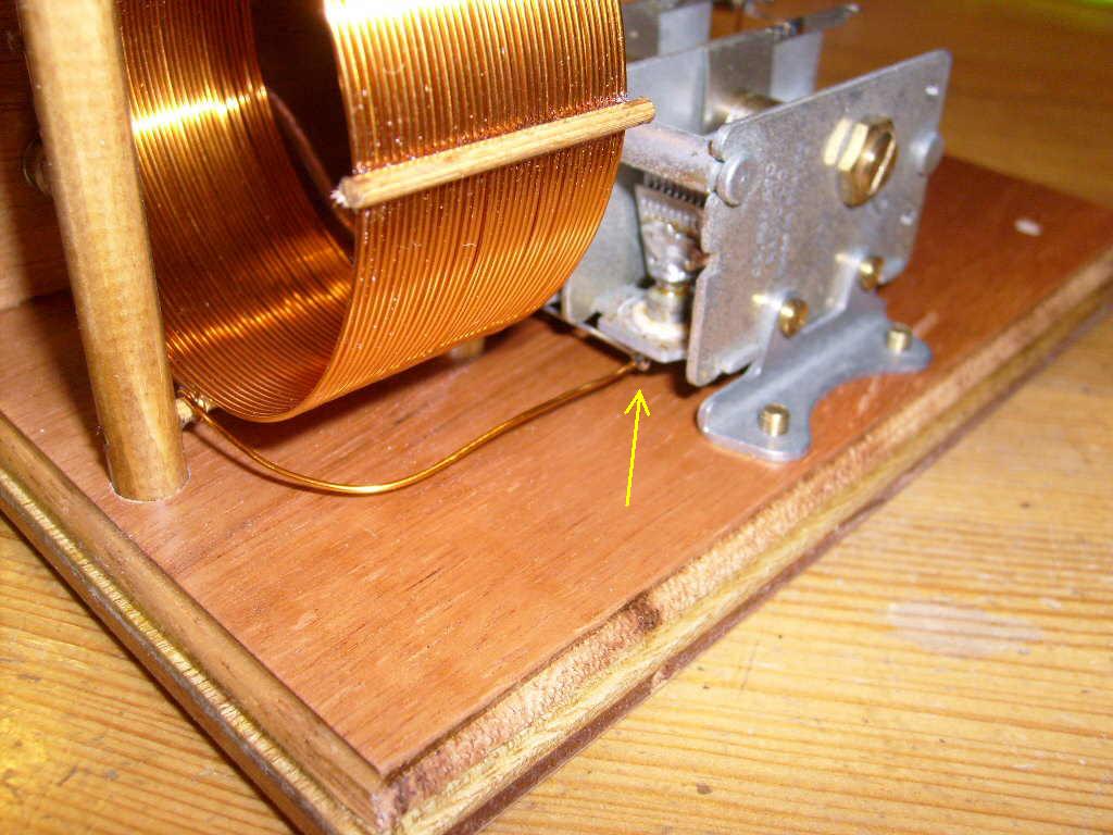
One coilwire runs underneath the tuning capacitor, is then bend upwards and cut
to length.
Solder this wire to the tuning capacitor (indicated with the arrow in the above
picture).
Scrap of the lacquer from the wire, before soldering.
The other wire is cut to length, and soldered to the solder tag of the tuning
capacitor (indicated with arrow).
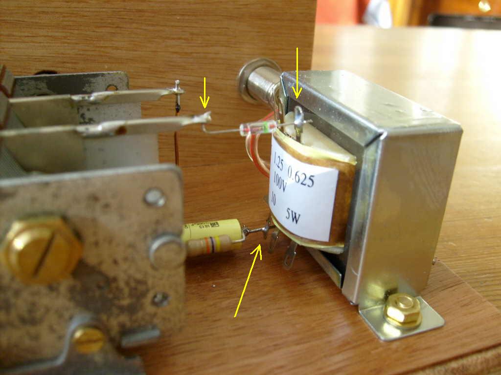
Place the transformer on the frame, fix it with two M4x16 screws, 2 rings and 2
nuts
The wire of the 68 nF capacitor must stick through the "0" connection of the
transformer, and is then soldered.
Solder the OA95 diode between tuning capacitor and the "0.625W" connection of
the transformer.
The green band on the diode must point towards the transformer.
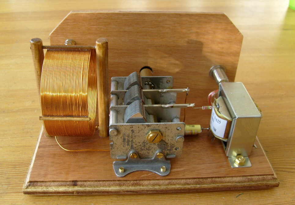
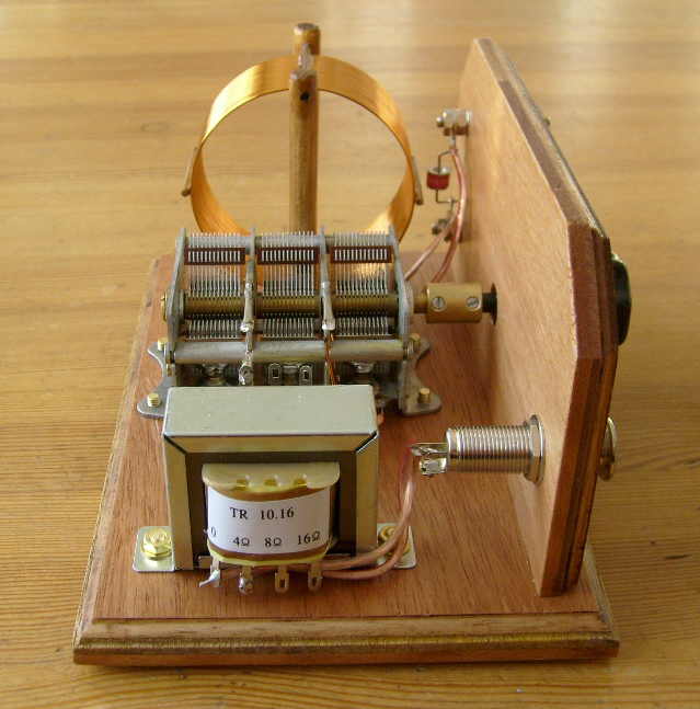
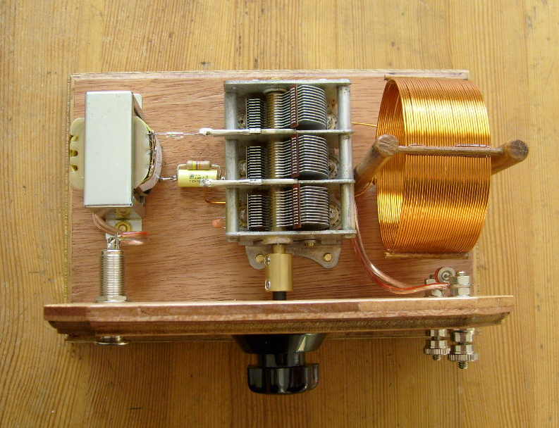
Overview of the components.
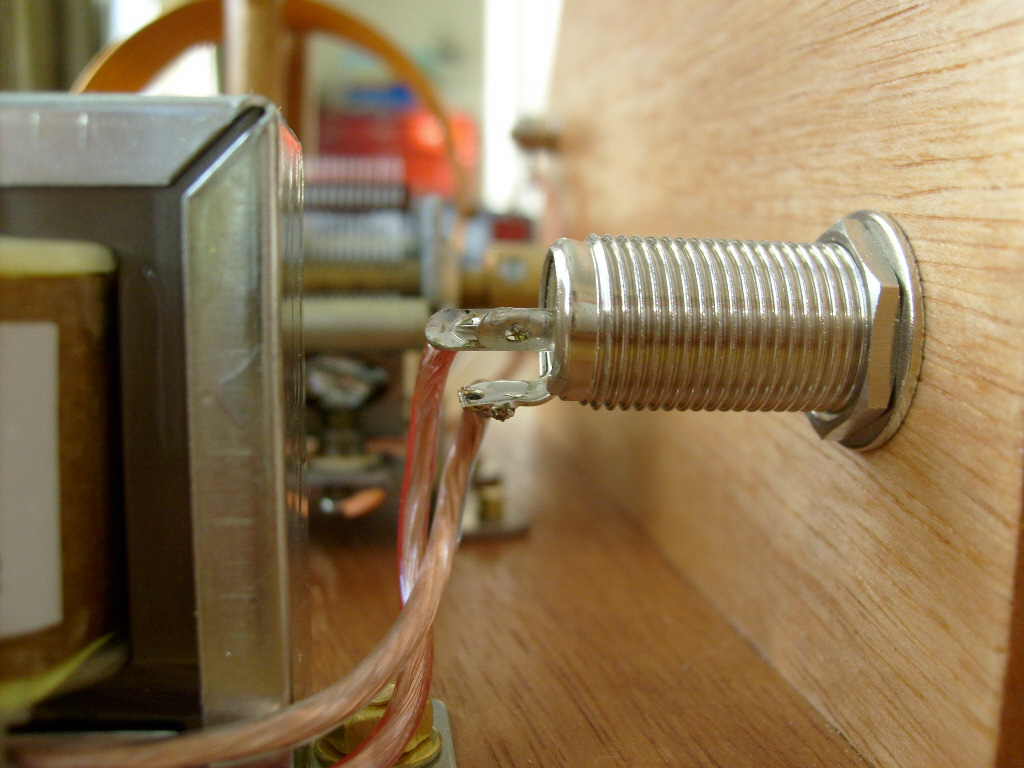
Solder the two wires from the transformer to the headphone socket (see for
detail: next picture).
Solder the two wires from the tuning capacitor to the terminal posts.
The wire with the red line on it, comes on the upper (antenna) connection.
The wire without red line, comes on the lower (ground) connection.
Detail of the wires on the headphone socket.
The wire without red line comes on the ground connection.
The wire with the red line comes on the two signal pins, so these two signal
pins are connected together.
Mount the extension shaft and the knob on the tuning capacitor.
In the middle position, the pointer on the knob must point upwards.