Crystal receiver set 2
This receiver has 2 tuned circuits, namely the antenna
circuit (L2 C1) and the detector circuit (L3 C2).
Coil L1 is an antenna coil, aiming to bring a short antenna wire to resonance,
so there would be more energy available.
In practice I did not found much improvement by using L1.
The antenna signal is coupled to the tuned antenna circuit by means of switch S2b.
The best selectivity can be obtained with switch S2 in a
low position (position 1, 2 or 3).
With switch S2 in a higher position the selectivity is lower, however, the sound
volume may increase.
With switch S2 position 1 to 8 the antenna circuit is in parallel resonance.
With switch S2 in position 9 the antenna circuit is in series resonance, I added
this position for experiments.
Detection is done by a germanium diode AA119. I tried
several types of germanium diodes, but this one gives the loudest reception.
There are two audio transformers, with the primary windings connected in series,
so the total primary impedance is 2x16 kΩ
= 32 kΩ.
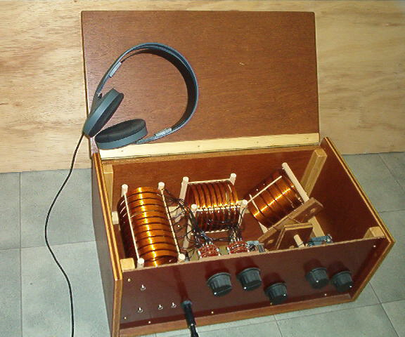
The coils are made of solid 1.0 mm enamelled wire, the coils are supported by wooden sticks.
Coil L3 can be rotated. With L3 almost vertical, the coupling with L2 is minimal, the selectivity of the receiver is then high, but the volume is low.
The output impedance is 16 or 32
Ω, which can be selected
with a switch.
The headphone impedance can be 32 or 64
Ω per side (2 speakers
parallel).
The receiver needs a wire antenna, preferably long and
high.
With a 10 meter long antenna wire, a lot of stations can be heard.
The receiver must also be connected to a ground connection, a 1 meter metal pin
in the ground works quite well.