
Antenna unit 1
Back to the index
Here a description of a antenna tuner unit.
It is used in combination with a detector unit (e.g.
detector
unit 1 ) , so a double tuned receiver is formed.
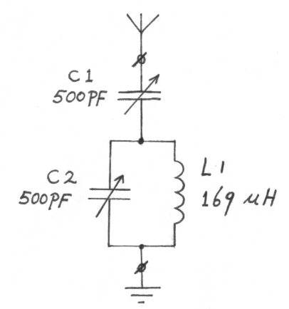 |
Schematic of the antenna unit. |
The antenna unit has a tuned circuit L1, C2.
If we only look at L1 and C2, then the tuning range is 550
- 2184 kHz.
But if we also connect the antenna and earth, the frequency of the circuit will
decrease, so we can also receive the lowest mediumwave frequency of 530 kHz.
Variable capacitor C1 and the antenna and earth are also a part of
the tuned circuit, but the antenna and earth also give reduction of circuit Q.
The circuit L1,C2 has a high impedance (e.g. 1 M.Ohm).
But the antenna has a low impedance (e.g. 10 Ohm), tuning capacitor C1 forms a
impedance match between this high and low impedance.
With a certain value of C1, there will be maximum power transfer from antenna to
the circuit L1,C2.
Then there is maximum voltage across the coil L1, and maximum sensitivity of the
receiver.
At low frequencies we must for instance adjust C1 to 100 pF, and at high
frequencies to 20 pF, but these values are depending on the (length of) antenna
we connect to it.
For the circuit Q however, the lower the value of C1, the higher the Q.
More information about this, you will find here.
Coil L1 is wound with litzwire 660x 0.04mm (660/46 AWG), on a polypropylene
former.
This coil is described here as coil L12, only
the outermost winding is removed to reduce inductance a little bit.
This reduced the total wire length from 15 to 14.5 meters.
The frame of this antenna unit is made of 8mm polyethene sheet.
Tuning capacitor C2 is driven via a 1:5 vernier drive, so we can tune it very
accurate.
Tuning capacitor C1 has no vernier drive.