Experiments with a antenna tuner unit
Here some measurements done with my "antenna unit 1".
|
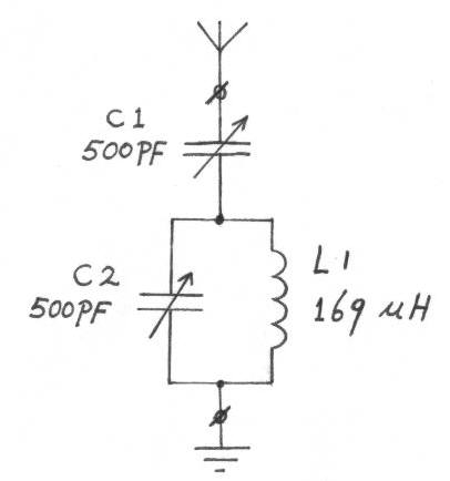
Schematic of the antenna unit 1. |
During the measurements the antenna unit is connected to the signal generator via a dummy antenna.
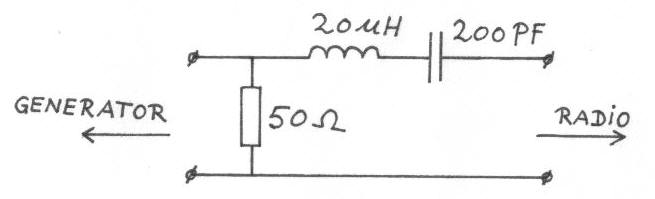 |
The dummy antenna. Made with a resistor of 50 Ohm, a coil of 20 uH, and a capacitor of 200 pF. The 50 Ohm output resistance of the signal generator is in parallel with the 50 Ohm resistor. |
The dummy antenna makes the receiver input is driven with a impedance of
25 Ohm in series with 20 uH in series with 200 pF.
This is about the impedance of a average longwire antenna.
With the dummy antenna connected to the generator (but without the receiver connected), the output voltage of the generator is adjusted to 50 mV peak-peak.
Now with various settings of C1, the frequency range of the circuit, the
voltage across coil L1, and the Q (across coil L1) are measured.
The measured voltages are Volt peak-peak.
The frequency range can be slightly influenced by the
measuring amplifier
wich was connected across coil L1.
| f min kHz |
f max kHz |
600 kHz Volt Q |
900 kHz Volt Q |
1200 kHz Volt Q |
1500 kHz Volt Q |
|
| Unloaded circuit | 550.0 | 2184 | Q=1111 | Q=1084 | Q=961 | Q=766 |
| C1=21pF | * | * | * | * | * | 5.15 V Q=410 |
| C1=25pF | 541.3 | 1661 | 2.30 V Q=983 |
4.15 V Q=789 |
5.00 V Q=528 |
5.0 V Q=346 |
| C1=26pF | * | * | * | * | 5.05 V Q=510 |
* |
| C1=35pF | 537.0 | 1498 | 2.90 V Q=895 |
4.65 V Q=616 |
4.90 V Q=382 |
4.55 V Q=214 |
| C1=47pF | * | * | * | 4.72 V Q=526 |
* | * |
| C1=50pF | 532.8 | 1484 | 3.55 V Q=800 |
4.70 V Q=471 |
4.40 V Q=245 |
* |
| C1=75pF | 525.1 | 1330 | 4.00 V Q=625 |
4.30 V Q=292 |
3.60 V Q=141 |
* |
| C1=100pF | 519.3 | 1237 | 4.05 V Q=526 |
3.80 V Q=226 |
3.00 V Q=98 |
* |
| C1=125pF | 514.1 | 1117 | 4.00 V Q=431 |
3.50 V Q=174 |
* | * |
| C1=150pF | 509.7 | 1078 | 3.80 V Q=380 |
3.20 V Q=140 |
* | * |
| C1=175pF | 505.9 | 1045 | 3.70 V Q=337 |
2.95 V Q=116 |
* | * |
Table 1: frequency range of the circuit, voltage across the coil and circuit
Q as a function of the capacitance of C1.
*= not measured.
With a certain value of C1, the voltage across the coil will be maximum, these
voltages are indicated with a green colour, on these points the Q is about halve
the value of the unloaded Q.
The minimum capacitance of C1 is 21 pF, at high frequencies this still looks too
much.
The maximum capacitance of C1 is 500 pF, but a maximum capacitance of 200 pF
already seems to be enough.
The highest circuit Q, so the best selectivity of the receiver occurs with the
lowest capacitance of C1.
This is not the same as the point of maximum voltage across the circuit.